Advanced Technical Training on Ball Valves for Natural Gas
Goals for this module
- Explore the design options for Ball valves
- Review the materials typically used
- Understand how valves are tested
- Learn about the valve best practices
------------------------------------------------------------------------------------------------------------
INTRODUCTION
In this training module we will focus on ball valves for on-off service (block valves) for Natural Gas applications.
We will provide some technical information that will allow you to evaluate the features of a valve.
Before starting this training, we recommend that you complete the "Introduction to Block Valves (On-Off Valves)", which is available on the BROEN.us website.
------------------------------------------------------------------------------------------------------------
DESIGN OPTIONS FOR BALL VALVES
Floating v. Trunnion Mounted
The main two types of ball valves are Floating ball type and Trunnion Mounted.
- Floating Ball Valve
- Design: In a floating ball valve, the ball (the spherical closure element) is not fixed in place; it is free to move or float within the valve body. The ball is typically held in position by two valve seats, one on the upstream side and one on the downstream side of the ball.
- Sealing: When the valve is closed, the pressure from the fluid forces the floating ball against the downstream seat, creating a seal and preventing the flow of fluid. This design of ball valve relies on the pressure from the fluid to maintain the seal. This implies that the higher the pressure, the higher also the torque required to operate the valve.
- Applications: Floating ball valves are commonly used in low-pressure applications.
Example of a BALLOMAX Floating Ball valve
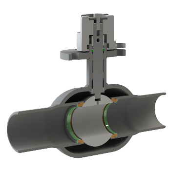
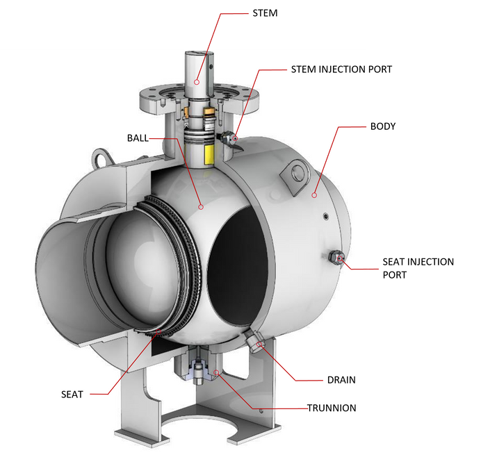
- Trunnion Mounted Ball Valve
- Design: Trunnion mounted ball valves have a different design. In this type of valve, the ball is fixed in place and supported by a trunnion, which is a fixed shaft or stem at the top and bottom of the ball.
- Sealing: Trunnion mounted ball valves often have multiple seats, including the upstream and downstream seats and sometimes auxiliary seats. This configuration allows for more reliable sealing and prevents the ball from moving under high pressure. The torque required to operate the valve is largely independent from the pressure in the system.
- Applications: Trunnion mounted ball valves are commonly used in applications where there are higher pressures involved. They are commonly used for large size valves, generally larger than 8".
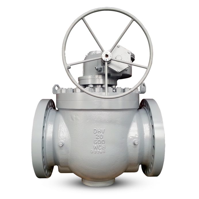
Example of a BALLOMAX Trunnion Mounted Ball valve
Body Options
There are three main options for bodies for ball valves:
- Welded-body valves: all body components are welded together and they cannot disassembled. This option minimizes the risk of body leaks. It is the preferred solution for valves for buried service, meant to go underground.
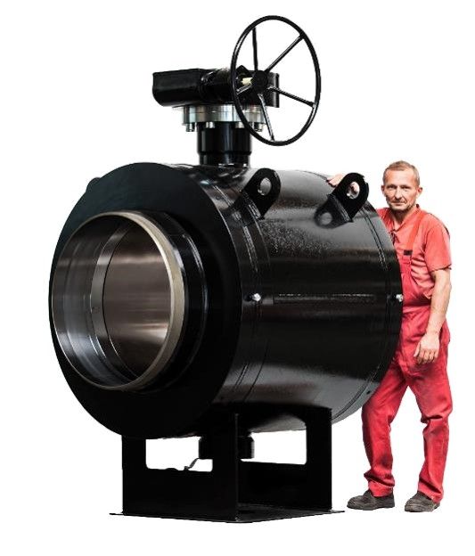
Welded body valve
- Side-entry bolted body valves: the end connections are bolted to the main valve body with bolts and nuts. This option allows for disassembling the valve for repair and or maintenance, when convenient.
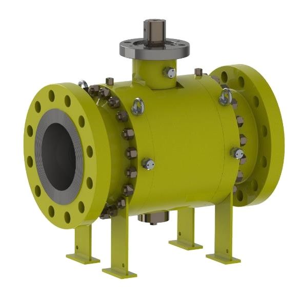
Side-entry bolted body valve
- Top-entry bolted body valves: the top cover (bonnet) is bolted to the rest of the body. This design allows access to internal components for maintenance or repair, without removing the valve from the pipeline.
Top-entry bolted body valve
Full port v. Regular port
Ball valves can be categorized based on the size of the bore within the closure member, commonly referred to as "port size".
- When the bore size matches that of the pipe, the valve is known as a "Full Opening Valve" also referred to as "Full Port".
- If the bore size is smaller than that of the pipe, the valve is referred to as a "Reduced Opening Valve", sometimes known as "Regular Port".
It is important to note that valves featuring non-circular openings within the closure member should not be classified as full opening valves.
Furthermore, valves with a reduced opening result in a more significant pressure drop across the valve compared to full opening valves.
Seat options
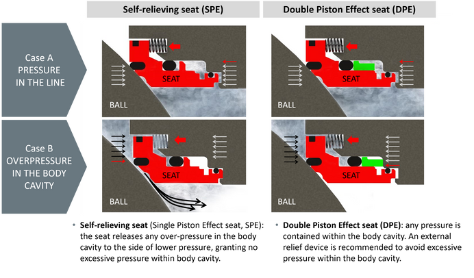
Self-relieving seats (aka "Single Piston Effect" seats, or SPE seats) and Double Piston Effect seats (DPE seats) are two different designs used in ball valves. The difference is in the way they handle an overpressure inside the body cavity.
Note: the body cavity is the space (or chamber) inside the valve, between the ball/seats and the valve body
- Self-relieving seats are designed to relieve excess pressure that builds up in the valve body cavity when it is in the closed position.
- Double piston effect seats are designed to create a seal in both the upstream and downstream directions. Any pressure inside the valve body cavity is contained. An external relief device is recommended to avoid excessive pressure in the body cavity.
Isolation features - Double Block and Bleed (DBB) and Double Isolation and Bleed
The best way to introduce these concepts is by using the definitions of API 6D.
What is API 6D? API 6D is the valve specification that provides guidelines for the design and manufacture of valves for Oil & Gas applications.
Double Block and Bleed (DBB)
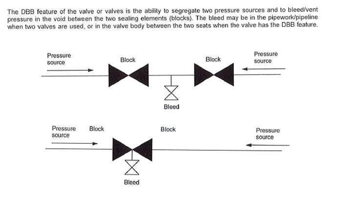
Please note that typically all Trunnion Mounted Ball valves provide DBB isolation, no matter what type of seats they are equipped with (SPE or DPE).
Floating ball valves are usually not DBB valves.
Double Isolation and Bleed (DIB)
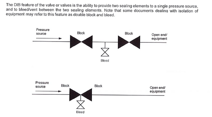
Please note that for a Trunnion Mounted Ball valve to provide DIB isolation, it typically has to be equipped with DPE seats; Trunnion Mounted Ball valves with SPE seats don't provide DIB isolation. API 6D distinguishes two types of DIB valves: DIB-1 and DIB-2. DIB-1 requires both seats to be bidirectional. DIB-2 requires one bidirectional seat and one unidirectional seat.
Floating ball valves are usually not DIB valves.
------------------------------------------------------------------------------------------------------------
MATERIALS
Steel v. Plastic Valves
In Natural Gas distribution valves are typically made of steel or plastic.
The plastic valves are made in Polyethylene (PE) and they are made in compliance with ASME B16.40.
In this module we will focus on steel valves. If you are interested in knowing more about PE valves, please check the dedicated training module on the BROEN.us website.
Steel materials: Forged v. Cast steel
Forged steel and cast steel are the two main methods of manufacturing steel components, each with its own set of characteristics and advantages. Here's a comparison between forged steel and cast steel:
- Forged Steel
-
Manufacturing Process: Forging is a manufacturing process that involves shaping heated metal using compressive forces, typically with the use of dies and hammers or presses. Forged steel components are created by carefully shaping and deforming a solid steel billet or bar under controlled conditions.
- Applications: forged parts are typically used when superior mechanical properties are required. Forged parts have reduced likelihood of defects.
- Steel grades: example of forged steel grades include A105, A350, P235GH.
-
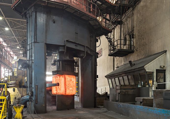
Picture of the forging process
- Cast Steel
-
Manufacturing Process: Cast steel components are formed by the solidification of molten steel. Casting involves pouring molten metal into a mold then allowing it to cool and solidify. The resulting steel component takes the shape of the mold.
- Applications: castings can be done for parts of virtually any size or complexity level. Casting is an easier method for larger sizes and more complex geometries that are difficult to achieve through forging.
-
Casting may have porosity issues and may require careful inspections and eventually repairs.
-
- Steel grades: example of cast steel grades include A216 WCB, A216 WCC, A352 LCC.
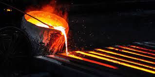
Picture of the casting process
Material Test Reports (MTRs)
In order for a valve to comply with API 6D requirements, the valve manufacturer is expected to provide MTRs for all the pressure controlling and pressure containing steel components.
MTRs are certificates prepared by the steel supplier that include the material grade, specification, testing performed, mechanical properties, and chemical composition for a specific heat number (which is a production batch).
MTRs are not a pressure test certificate.
Seat Materials
When it comes to seat materials, the selection is mainly driven by the process conditions (i.e. fluid, temperature, pressure) and manufacturer's/user's preferences. The most common options are:
- Soft seats:
- This is the most common option for low pressure, low temperature applications, with non-aggressive fluids.
- The materials are usually:
- Rubber/Elastomers. For example, HNBR (Hydrogenated Nitrile Butadiene Rubber, also known as simply "Nitrile")
- Thermoplastics. For example, PTFE (commercially known as "Teflon")
- Metal-to-metal seats:
- This option is used for severe services, like high pressure, high temperature applications, and/or with aggressive fluids or with suspended solids.
- Primary Metal Secondary Soft (PMSS) seats:
- PMSS seats combine the benefits of the two previous options. In this option the seat has two points of contacts with the ball. One is metal-to-metal and it ensures performance even with aggressive fluids; the second one is soft and it ensures tight shutoff.
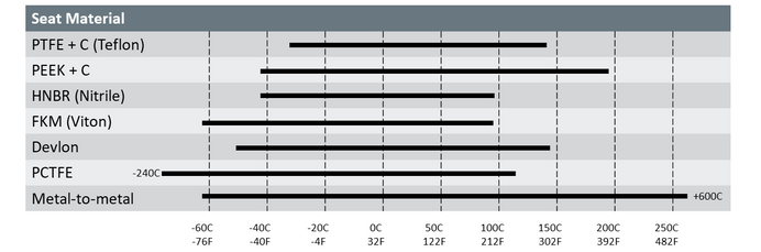
Simplified table showing the temperature ranges for selected seat materials.
Please note that different compounds can be described with the same simplified commercial name. Please ask your supplier for a data sheet showing the properties of the specific compound you are purchasing. The properties should include fluid compatibility, temperature range, pressure range.
------------------------------------------------------------------------------------------------------------
VALVE TESTS
Ball Valves for Natural Gas service can be tested in many ways according to several test standards and codes. In this section we will explain the most common test required in the industry.
Shell Test and Seat Test
According to API 6D every valve shall be subjected to hydrostatic pressure tests.
For these tests the test media shall be water with the addition of a rust inhibitor.
The first pressure test is a shell test aimed at detecting any external leaks, outside the body. For shell test, the test pressure shall be a minimum of 1.5 times the valve pressure rating. The minimum test duration is defined by a table in API 6D and it depends on the valve size. There shall be no visible leakage permitted during the hydrostatic shell test.
Each seat shall be subject to a hydrostatic pressure test. The goal is to detect any seat leakage. For seat test, the test pressure shall be a minimum of 1.1 times the valve pressure rating. The minimum test duration is defined by a table in API 6D and it depends on the valve size. The test acceptance criteria depends on the seat materials. For soft seated valves, there shall be no visible leakage during the hydrostatic seat test.
The valve purchaser may specify additional shell test or seat test. The typical requests include: an extended test for a duration longer than the one required per API 6D; low pressure air test; tests to verify DBB isolation and/or DIB isolation.
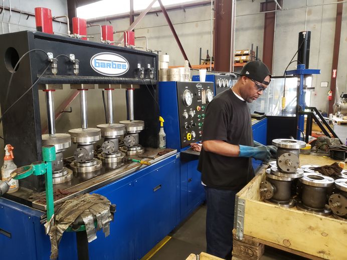
Valves being hydrostatically pressure tested per API 6D at BROEN Houston facility
Fire Test
Compliance with a fire test standard may be required to ensure that a ball valve meets industry safety requirements and can temporarily function during fire emergencies. Once a valve passes a fire test, it is commonly defined as a "fire-safe" valve.
During a fire test a valve is subject to extreme heat for a specific time period and it is required to be able to keep providing sealing and prevent the release of flammable or hazardous materials during a fire event.
Typically, fire-safe valves have metal-to-metal seats or PMSS seats and have redundant graphite rings to ensure sealing performance.
The main fire test codes and standards for Oil & Gas applications are API 607 - Fire Test for Soft-Seated Quarter-Turn Valves; API 6FA - Fire Test for Valves; ISO 10497 - Fire Test for Valves. The test procedures and acceptance criteria for these standards are very similar and these codes can be considered equivalent.
A fire test is a design validation test, not a production test. As such, it is not required to be done on each valve manufactured.
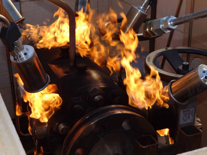
A valve subject to fire test
Fugitive Emissions Test
A fugitive emission test for ball valves is a specialized evaluation conducted to measure and assess the leakage of volatile organic compounds (VOCs) or hazardous gases from the valve's stem and sealing components. This test is critical in industries where the containment of fugitive emissions is essential to maintain safety, environmental compliance, and worker health.
Typically, a fugitive emissions test involves subjecting the valve to specific conditions, including temperature and pressure cycles, to evaluate its sealing performance under simulated real-world conditions, including several pressure cycles (high pressure, low pressure) and frequent valve opening-closing operations.
The main fugitive emissions test codes and standards for Oil & Gas applications are ISO 15848 and API 641.
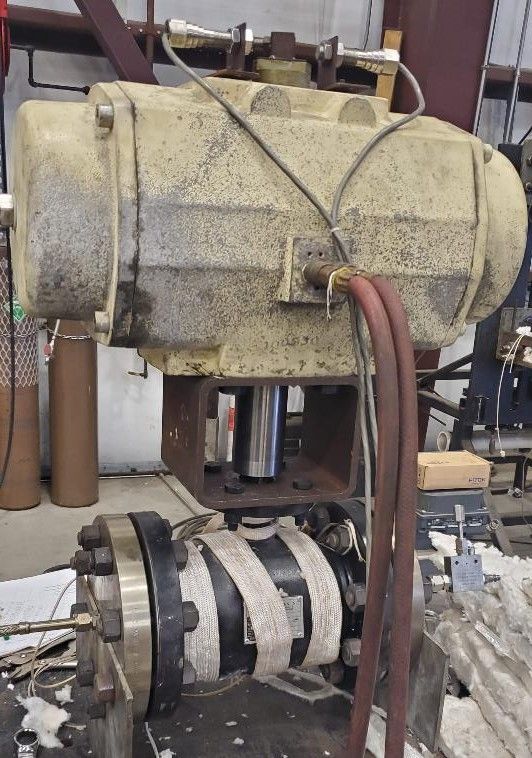
A BROEN BALLOMAX valve during an API 641 fugitive emissions test
------------------------------------------------------------------------------------------------------------
VALVE BEST PRACTICES
The following section includes some best practices related to ball valves. The following information is not comprehensive and generic, and it does not replace the information that should be provided by each valve manufacturer for every specific valve.
Valve Selection
Most of the problems with valves can be avoided by selecting and purchasing the right valve. It seems obvious but it is not. Before selecting a valve, make sure to have a clear understanding of what you need, in terms of:
- Service: what is the purpose of the valve? Allowing or stopping the flow? Regulating the flow? Avoiding over-pressuring the system?
- Fluid: do you know the fluid? Its process conditions (max/min temperature; max/min pressure)?
With this basic set of information, you should be able to select the proper valve type.
- Specification: do you have a valve specification? Do you know which standards/codes your valve should meet?
- Dimensions and end connections: do you have such information? Did you share it with your valve supplier?
Valve Handling and Storage
Frequently, damage to valves is caused prior to using the valve, during transportation from the valve factory to the job site or when the valve is stored in a warehouse.
Typically, valve companies have an Operations and Maintenance manual that includes their recommendations about valve handling and storage.
A few general recommendations for ball valves include:
- Transport the valves with the ball in the open position.
- Lift the valves using lifting lugs. Do not lift from flanges, from the actuator or from the handwheel.
- Make sure your valves are supplied with end caps/flange covers and with a protective plastic wrapping that protect the valve's internal parts from contamination.
- Verify valves are transported in their original shipping packaging and properly secured to their pallets and to the vehicle.
- Avoid storing the valves outdoor exposed to weather conditions and sunlight.
Valve Installation, Welding, Commissioning
Recommendations for welding WxW ball valves:
- Weld with the ball in open position.
- Consider using an anti-spatter spray to prevent the spatter bbs from sticking to your valve internals.
- Avoid excessive heat that can damage the soft parts in your valves. Each manufacturer has its own recommendations to avoid over-heating.
- Use the proper welding procedure.
When commissioning a pipeline system, make sure that all the valves are in open position.
Valve Use
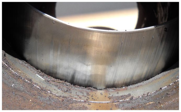
If you are using a block valve, do not leave it in a partially open position, and do not use it for throttling. Leaving a block valve in the partial open position can damage the seating surface of the valve. These situations may also cause cavitation, which can severely damage the valve.
What is "cavitation"? Cavitation in ball valves occurs with liquid fluid when the valve is partially open, creating high-velocity flow in a narrow passage. This lowers the pressure, causing vapor-filled bubbles to form. When the pipe section increases, the bubbles collapse, potentially damaging the valve and nearby components due to the sudden localized pressure increase.
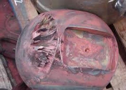
When operating a valve, make sure not to exceed the torque limits. Over torquing a valve can cause damage (e.g. breaking the valve stops). As a rule, for manually operated valves, the force required at the handwheel or wrench should not exceed 80 lbf (360 N). A "cheater bar" should never be used to operate a valve. Please note that ball valves are "position-seated" valves (as opposed to "torque-seated" valves, like most gate valves, where "the tighter the Valve, the Better It Seals.”).
Valves are the biggest single cause of pigging problems. Full bore valves are essential. Wedge gate valves or plug valves are not piggable. Valves must be in open position when pigging. Flush and lubricate valves after pigging (see below).
What is "pigging"? "Pigging" is a critical pipe integrity process. It involves using a device called a "pig" to clean and/or inspect the pipeline, ensuring its safe and efficient operation. The pig is propelled through the pipeline by the flow of gas, and it can remove debris and detect defects.
Valve Maintenance
Ball valves are considered a low maintenance equipment. However, some basic maintenance is recommended.
In the USA, the Pipeline and Hazardous Materials Safety Administration (PHMSA) released Title 49 Part 192 of the Code of Federal Regulations (CFR). It contains regulations related to the transportation of Natural Gas by pipeline. This very important document includes the following requirements:
- 192.745 Valve maintenance: Transmission lines: “Each transmission line valve (…) must be inspected and partially operated at intervals not exceeding 15 months, but at least once each calendar year”.
- 192.747 Valve maintenance: Distribution systems: “Each valve (…) must be checked and serviced at intervals not exceeding 15 months, but at least once each calendar year”.
We recommend that all valve users follow these requirements.
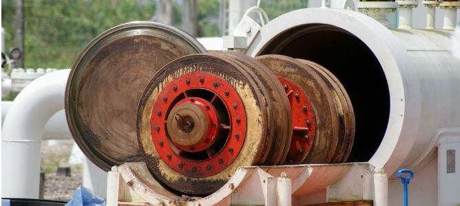
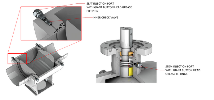
Some ball valves have injection ports on the seats and/or the stem.
These ports can be used to inject chemicals in the sealing are, with three different purposes:
- Flushing. The goal is to clean the sealing area by removing any debris. Flushing is recommended after commissioning, after pigging, and whenever valves are not operated for a long time.
Please note that flushing is recommended in the seat area, but it is not recommended in the stem area. - Lubrication. The goal is to reduce the torque required to operate the valve.
Please note that lubrication is recommended in the seat area, but it is not recommended in the stem area. - Emergency sealing. When the valve is damaged and cannot provide the required sealing performance, injecting a emergency sealant can improve the sealing and stop leaks.
Make sure to inject chemicals with the proper composition into your valves. Please refer to the valve manufacturer or the chemicals manufacturer to make sure of your selection.
Make sure to inject the appropriate quantity of chemicals at the right pressure, to make sure your operation will be effective without damaging the seals.
If you have any doubts or concerns about valve Operations and Maintenance, contact your valve manufacturer and ask for support.
------------------------------------------------------------------------------------------------------------
Congratulations for completing this training module!
Check your knowledge by taking a test.
You will receive a training certificate by email upon completion.
Start the test by clicking the button below.

------------------------------------------------------------------------------------------------------------
If you have any comments on this training module, please reach out to us at info@broen.com